Combine Multiple Bodies to Create a Single Body, in a Multibody Part
CAD Geometry Customized Modeling in Ansys Mechanical WP (via APDL)
Seasoned, veteran users know that you run a small risk of stress blips very near a region where contact is defined. It’s a nature of the beast and a result of the numerical activity taking place as the contact and target elements interact with each other. This resource guide will provide all you need to know about CAD geometry in Mechanical WB.
Bonded Contact in CAD
Specifically I’m referring to the use of bonded contact in this article, although other contact behavior types run the same risk. Sometimes, this may be no issue if the region is not of interest, but sometimes it can be an issue. There are several alternative ways to make adjacent bodies interact without using contact.
What is the Node Merge Option?
Users might take advantage of the newer Node Merge option that was released in v16.0 of Workbench (WB) Mechanical. Another common alternative that’s been around longer is to simply group CAD bodies into a “multibody part” (MBP), which then forces Mechanical to recognize their connectivity and interaction with each other. This is again very similar to a merging action where single nodes take care of the connectivity of adjacent elements from adjacent bodies.
What if i don’t have a license for DesignModeler or SpaceClaim?
In this latter case of creating MBPs, you’re stuck if you don’t have a license for DesignModeler (DM) or SpaceClaim Direct Modeler (SCDM), both being the front-end CAD packages available in the Ansys product lineup, and both having the ability to create bona fide MBPs that Mechanical recognizes.
Forcing Connectivity between CAD Bodies when Contact is Unavailable
Many other CAD packages create “assemblies, parts, or groupings” of some type, but none are recognized as MBPs in Mechanical, except when done so by DM or SCDM. This article presents a workaround available to force connectivity between CAD bodies when using contact is not an option and when a DM or SCDM license is unavailable.
Differing Modeling Types: Solid Model and Finite Element (FE) Model
I would like to first briefly explain two basic aspects when discussing modeling in Ansys: solid model and finite element (FE) model. Behind the scenes, the software recognizes these two aspects separately. The former is the typical solid CAD model that most would be familiar with from a drafting software package, such as SolidWorks or Inventor. It is comprised exclusively of volumes, areas, lines, and keypoints (a.k.a.: vertices).
Exclusive use of Nodes and Elements
On the other hand, the FE model is comprised exclusively of nodes and elements. The discussions in this article focus on some modifications to the CAD model, followed by generation of the FE model from the modified CAD, which culminates in Mechanical having an FE model derived from a new merged solid model. No aspect of the solid CAD model is ever sent to the Mechanical solver so the fact that the following process strips away the original native CAD is of no consequence, in terms of what the solver needs to see.
APDL Processing and Command Snippets
Moreover, savvy Mechanical users who know how to use Command Snippets therein, should recognize that the following APDL process cannot be substituted with gluing Command Snippets in WB Mechanical, again because the Mechanical solver has no awareness or recognition of the solid CAD aspect of the model.
Import, Glue, and Mesh Model in Mechanical APDL
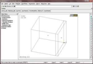
Mechanical APDL has glue commands therein, which allow a user to “glue” together (i.e., bond them as would be the case for bonded contact) pieces of the solid model. This works for 3D as well as 2D models also. The first step is to import the CAD model to Mechanical APDL. From within Mechanical APDL, options are available to import various CAD file formats, as shown below. Some formats require an additional license though. But since the whole objective here is to create connectivity in the absence of certain licenses, note that most (if not all) CAD packages export to generic formats that APDL can read without an additional license (e.g., IGES).
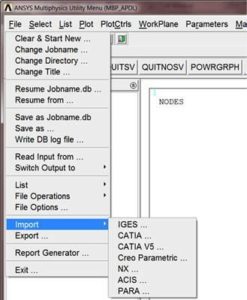
The figure shows an example of two volumes (V1 and V2) that have been imported from a Parasolid CAD file. Once the CAD model is loaded in APDL, you can proceed to glue pieces of the model together.
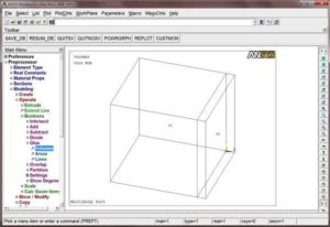
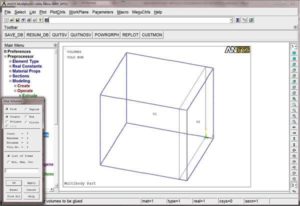
Once the Boolean glue operation has been selected from the menu tree, you can pick the volumes (or areas or lines) to merge together as shown below.
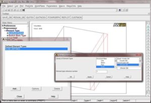
Once pieces are glued together how you want them, we will proceed to mesh the model. It is first necessary to define an element type for the APDL mesh tool. This is needed at the least, for the APDL mesher to apply a mesh to the CAD model. The element type can again be accessed from the preprocessor menu tree as shown below. Although subsequent steps here in APDL will apply a mesh to the model, it’s important to understand what will happen to the mesh later when back in WB Mechanical. A few different outcomes can occur and that outcome is dependent upon your decision later to retain the APDL mesh in Mechanical or re-mesh in Mechanical (more discussion later on re-meshing in Mechanical). The elements and nodes created here in APDL will later be transferred over to Mechanical.
Understanding Default Node Brick Element Inputs
However, supposing you retain the APDL mesh, the choice of element in APDL will be overridden in Mechanical. For example, if you choose SOLID45 elements (8-node brick) in APDL, Mechanical will acknowledge that the bricks have only 8 nodes (as opposed to 20), but when ready to solve, it will instead apply its default 8-node brick element, which at the time of this writing, is SOLID185 elements. Likewise for a 20-node brick example; i.e., a SOLID95 20-node brick chosen in APDL will instead become SOLID186 when Mechanical is ready to solve the model. However, if you re-mesh the model in Mechanical, it will apply the element type as dictated by the Mechanical mesh settings. For example, if you chose SOLID45 elements (8-node brick) in APDL and later in Mechanical, you proceed to re-mesh the model with its default settings, it will apply SOLID186s instead (20-node bricks) since all remnants of the APDL mesh get completely abolished in that scenario. Therefore, it’s not vital at this point that you select the most appropriate element type but be mindful of the outcome you may get later.
Ensure your Order Preference Aligns with your CAD Geometry
It would however, make the most sense, to at least select an element type that is of the order you prefer and also coincides with the type of CAD geometry you will be meshing; i.e., select a solid, shell, or beam element type for volume, area, or line CAD geometry, respectively.
We can now proceed to mesh the CAD model. The APDL meshing tools are primarily located in the Meshing branch in the preprocessor menu tree. There are many different options available to control the outcome of the mesh, most of which are beyond the scope of this article. However, for the simple model herein, I opened the MeshTool as shown below.

Under Size Controls, I set line controls on the various edges defining both blocks, after which it was meshed as shown below.
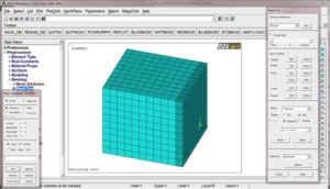
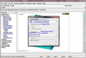
At this point, the two separate bodies have now been merged and meshed to create a scenario similar to that of a bona fide MBP from DM or SCDM; i.e., load transfer will occur through the interface of the two bodies without the need for contact. Now it is necessary to archive the APDL model to a .CDB file. In the preprocessor menu tree, choose Archive Model í Write as shown below. Click OK and the file will be written to the working directory.
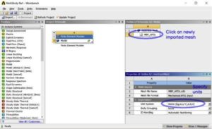
It is now necessary to open a Workbench project page. Place a Finite Element Modeler (FEM) component system on the project workspace. Right click on the Model cell and choose Add Input Mesh. Browse to the location of the .CDB file to load it. Right click on the CAD geometry or Model cell and choose Manage Input Meshes. An additional window will appear on the WB project page where you can specify the units that the model was built with in APDL (figure below).
Note: APDL is Unitless, Mechanical is Not
On a side note, savvy APDL users may know that APDL is actually unitless; Mechanical is not though. Despite that, in this step you must specify the intended units that the APDL model was constructed in. Note that in the Outline window, you can click Assembly Mesh at the top level and change the units for the FEM GUI. Doing so here will simply convert the FEM graphics window into another units system (e.g., 0.0254m cube can be shown as a 1 inch cube).
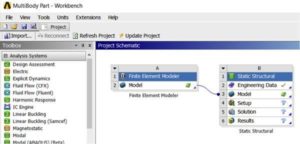
Return to the project page and place the desired analysis system on the work space. Then drag and drop the Model cell of FEM onto the Model cell of your new analysis system, to create a link as shown below.
Right click to Update/Refresh both CAD geometry/cells of FEM and Static Structural. Open WB Mechanical and you will now see the mesh that was previously created in APDL .
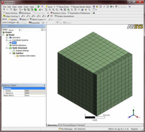
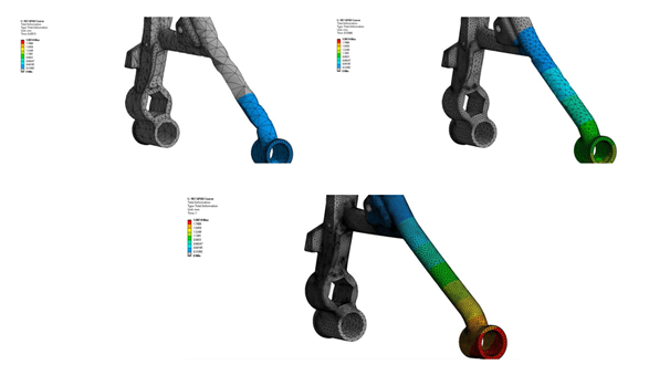
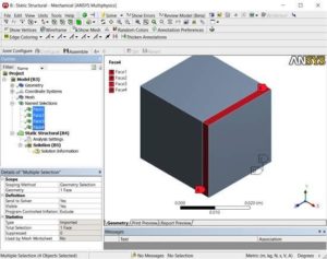
At this point, you now understand the overall process and so I want to further discuss the mesh that was created. As shown in the figure below, the original two blocks are gone and replaced with a single block; that is, you have now solved the main problem and created a continuum body removing the need for contact elements.
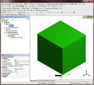
Applying Loads or Boundary Conditions
If you had intentions of applying loads or boundary conditions to one of the blocks separately, this could be a problem. The figure shows a delineation in the mesh, but the underlying geometry does not. This is a product of the CDB archival process, which strips away the underlying original solid geometry and replaces it with a CAD geometry synthesized from the generated APDL mesh. Furthermore, if you now re-mesh in WB Mechanical, the delineation will be completely stripped away as shown in the figure below. Read on to learn what you can do in FEM to help alleviate these issues.
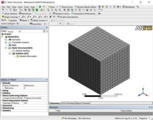
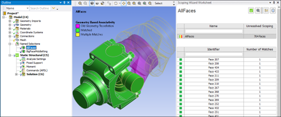
Presumably you only used APDL to glue the bodies into a single body; i.e., you created a pseudo multibody part. Perhaps you were not very savvy with the meshing tools therein and would like to redo the mesh in Mechanical. But as you already saw, any tampering with the mesh in Mechanical will completely strip away the last remnants of the original underlying geometry. You can do some work in FEM to create Named Selections, which will then carry over to Mechanical. Those Named Selections will then be available to apply mesh controls and/or boundary conditions, which helps you retain the remnant of the original geometry.
Back on the WB project page, you can double click the FEM Model cell to open the Finite Element Modeler. As shown, the upper toolbar of Finite Element Modeler contains selection tools to pick element faces. Once the desired faces have been chosen, you can right click in the graphics window and choose Add Component, which will create new components in the left model tree. These facial components will then pass directly to Mechanical as facial Named Selections, on which you can apply loadings or use for mesh sizing controls.
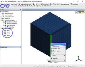
Creating the components in Finite Element Modeler enables you to retain geometry features that you may want to make reference to in Mechanical. And for those who are curious, the underlying process between Finite Element Modeler and Mechanical is to take the mesh in FEM and synthesize a CAD geometry from the mesh.
Reverse Engineering Mesh into a Solid Model
This can be thought of as “reverse engineering” of the mesh back into a solid model, which then manifests itself as geometry objects in Mechanical’s model tree. When FEM has facial components in its CAD geometry tree, those components force the synthesizing process to honor their existence, thus passing the facial aspects over to Mechanical for referencing later in mesh controls and/or boundary condition application.
Conclusions | Merging CAD Geometry & Bodies
So if you’re faced with a tough situation where using contact between bodies is unacceptable, but you don’t have any other way to define the interaction between bodies, some trickery can get you out of the woods. With a little effort, you can get your model loaded into APDL to then glue bodies together. Once they are glued and meshed, you can export the finite element mesh to a .CDB file. That .CDB file can be read into a Finite Element Modeler component system in Workbench. After retaining various geometry features in FEM, by creating facial components, you can pass the CAD geometry over to Mechanical, where the components become Named Selections. In Mechanical, you can make reference to those Named Selections for mesh sizing controls and/or load application. Although it may seem a little laborious, it could be a game-changer when you have no access to DesignModeler or SpaceClaim Direct Modeler to create a multibody part. So give it a shot!
- For guidance on Ansys Post-Processing
- For Support on performing ‘EKILL‘ in Workbench
- APDL Command Objects post-Spectral Analysis
- For Separating DB Database Files from RST Files
- Measuring Geometric Rotation in Mechanical WB
- CAD Geometry Deformation Plasticity