Customizing your Logo in Ansys Mechanical Workbench
Ever wonder about spicing up your graphical display for your next big project presentation, industry conference, or technical report? Tired of the routine Ansys graphics that you have installed out-of-the-box? Then this is the article for you.
Later versions of Ansys seem to be especially generic with the quasi Arial-Narrow font beaming at you from the corner of the GUI. Now you can spice things up and show your people that you’ve got it going on and are at the top of your class! Read on to learn how to change the Ansys logo that appears in the upper right corner of your Mechanical APDL or Workbench (WB) Mechanical interfaces. I will also show you how to display any image you want, as the full background in your Mechanical APDL interface. You can display whatever suits your fancy, from your dog Fido to your company logo!
![]()
Note that the following has only been performed in a Windows operating system (OS). Results may vary in Linux. Also, a link is provided at the end of this article to download some various sample files and images to help you.
Workbench Logo Change
Disclaimer: the following process only works for v14.5.7 and newer versions of Workbench. Additionally, depending on your company’s software installation policies, you may not have access to the correct files to make these changes. E.g., suppose you are running a remote network version installed by IT folks who hold the keys to the installation configuration, thus prohibiting you from tampering with it.
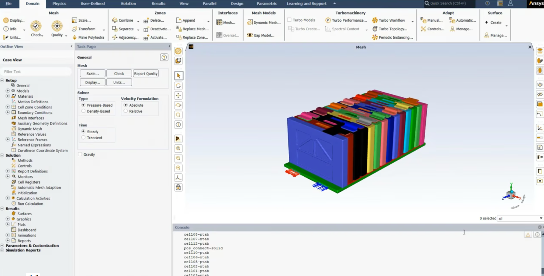
Several modules in WB display the mundane version logo in the upper right corner of the screen as shown below. For at least DesignModeler (DM), Mechanical, and Finite Element Modeler this can be changed by modifying the .PNG file that the software reads to display the logo and it is rather simple to do. For some other modules, the image may be loaded from a different directory location, which is beyond the scope herein.
![]()
Open Windows Explorer and navigate to the [ANSYSInstallDir]\v##\commonfiles\images directory (e.g., C:\Program Files\ANSYS Inc\v161\commonfiles\images). Locate ANSYS_blk_lrg.png. This is the file that WB reads when you specify the black logo in the software options (more on this later). At this point, it is suggested you rename the file to something like ANSYS_blk_lrg – ORIGINAL.png in the event you need to revert back to it later. Depending on your Windows OS and its settings, a pop-up may appear requiring you to provide administrator permission before the rename can take place. Click OK or Continue to grant the permission. In this directory, is where you will place your new final image, after you have prepared it according to the following discussion. That is, it is suggested to first prepare the image from another file location, such as the desktop before final placement in the Ansys program directory.
Note that the dimensions of the original file are 129 x 96 pixels. It is not imperative that your new image be the same dimensions. However, if it is excessively large, the image may consume a large portion of your WB work area and be visually overbearing. Try different sizes to determine what suits you best. Windows Paint software (among many other photo editors) can be used to resize an image larger or smaller.
Although not necessary, background transparency is another consideration when preparing your new image. As shown in Figure 3, the image does not have a transparent background, which produces poor aesthetics when the model is panned around and moved in proximity of the logo (i.e., the rectangular block of the image becomes visually apparent). This can be fixed in many popular photo editor packages such as Windows Paint with the transparency function therein. Another option is to insert the image into a dummy PowerPoint presentation and use its transparency picture editing function to create a transparent background. You then have the right mouse context option on the picture to Save As Picture. I have found the transparency function in PowerPoint to work rather well. Depending on the picture’s resolution and the software’s transparency functionality, the operation may produce shoddy results, giving a poor haze around the logo image when used in WB. The suggestion is to start with a higher resolution image so the color delineation between the image and the background is better defined. But be sure to size it properly first, as discussed earlier, since some software packages undo image transparency when follow-up operations are performed on the image, such as resizing. The result of a well-prepared image is illustrated below.
![]()
![]()
Once you have your image prepared and named correctly (ANSYS_blk_lrg.png), now place it in the aforementioned Ansys image directory. Again, you may need to provide administrator permission first before the move can take place. The rest is easy. Simply open WB and on the front project page, click
Tools → Options
Click Appearance in the left tree. Then specify the Ansys Logo as Black as shown below. You can also change other appearance options here, as desired. Click OK and now open DM, Mechanical, or the Finite Element Modeler to view your new image!
![]()
See the link at the end of this article to download various sample images to get you started.
APDL Logo Change
Like WB, the interface logo in APDL has gotten more mundane. This too, can be spruced up, but the process is a little different. The following method has been tested and used in v14.5.7 and newer versions of APDL. But considering that it is based upon the age-old APDL command scripting, it is likely that this process applies for many versions, new or old. The discussion below is based upon use of the start[###].ans file. Using this approach will make the logo appear every time you start a new session of APDL. However, the command language will also work outside of the start[###].ans file in the event you want to change the logo, but maybe only for a certain session or period of time within a session.
![]()
The start file is a customizable command file that is automatically read by APDL upon startup, if you choose to put it in your home directory and use it. Its file name is version specific (e.g., start145.ans, start150.ans, start160.ans, etc.). Sample startup files are available for users to build from in [ANSYSInstallDir]\v##\ansys\apdl. Copy this sample file to your home directory where Ansys will automatically look for it during startup. You can determine your home directory by opening Windows Explorer and typing %homepath% in the address bar. Once you have placed it in your home directory, you can now begin customizing the APDL startup processes by modifying the startup file. Specifically here, I am going to show you how to customize it to display different imagery in your GUI.
The default start[###].ans file has many example startup commands in it for a user to consider, all of which are initially commented out (with the ! line starter notation), but available for possible activation if you choose. You can also add your own commands if you choose to. Since everything is initially commented out and thus inactive, we can leave them alone and start our modifications at the very end of the file. Take a moment and decide where you might permanently store the new logo image and what you will name it. The decision is arbitrary, but for simplicity, I suggest storing it in your home directory where it will reside with your newly modified APDL startup file. However, there is no need to actually put it there yet. For now, begin modifying the startup file. The file should be opened and edited in a text editor, such as Notepad, WordPad, or the like. Insert the /TXTRE command. Type the first 3 fields verbatim, using the syntax shown below. For the fourth field, specify the file directory that you will store the new logo image in permanently. Enclose it with single quotes. The fifth and seventh fields should be specified as PNG, while the sixth field is left blank. The syntax should resemble this:
/TXTRE,FILE,51,’[permanent file location]\[logo file name]’,PNG,,PNG
Save and close the file in your home directory.
![]()
Now prepare your new logo image and store it in the location you previously decided upon, as a PNG format. As with the WB logo customization, be mindful of the pixel dimensions of your new logo. At the end of this article, is a link to download some samples that are on the order of 100-200 pixels wide by 30-100 tall. It is not imperative that your new image be the same dimensions. However, if it is excessively large, the image may consume a large portion of your APDL work area and be visually overbearing. Try different sizes to determine what suits you best. Windows Paint software (among many other photo editors) can be used to resize an image larger or smaller.
Also consider image background transparency when preparing the new logo, to enhance aesthetics. Reread the discussion in the preceding WB Logo section to glean more information about transparency.
Now simply launch an APDL session and watch the magic! By default, the software looks in your home directory for a start[###].ans file and executes the commands therein, if it finds any. If you have done everything right this far, the new logo should display in the upper right corner of the software when it opens. An example is illustrated below. Note the background of the new logo has not been set to transparent since the color scheme of the logo would not display well with the default black GUI scheme. The second example below however shows an Ansys logo having a transparent background.
![]()
![]()
APDL Background Change
Again using the /TXTRE command, you can modify the APDL background to show any image you would like, instead of the plain black background. This customization can be done by itself or in conjunction with the previously discussed logo change. You should use discretion with this background change since an image that consumes most of the background real estate may be overbearing and make it difficult to visually interrogate a model well. But it might still look good if perhaps you have faint, discrete imagery that you would like to show on the background that does not hinder model visibility (e.g., a faint shadowing of a company logo). It all boils down to how you prepare the image to be used. Although perhaps overbearing, an example of the outcome is shown below.
![]()
As mentioned before for the APDL logo change, this background change has been tested and used in v14.5.7 and newer versions of APDL. Again considering that it is based upon the age-old APDL command scripting, it is likely that this process applies for many versions, new or old. The discussion below is based upon use of the start[###].ans file. This approach will make the new background appear every time you start a new session of APDL. However, the command language will also work outside of the start[###].ans file in the event you want to change the background, but maybe only for a certain session or period of time within a session.
Reread the section for the APDL logo change to gain a basic understanding of the start[###].ans file, where to obtain a sample of it, and where to place it for use. Once you have it placed in your home directory, you can begin modifying it to display your new background. Take a moment and decide where you might permanently store the new background image and what you will name it. For simplicity, I suggest storing it in your home directory where it will reside with your newly modified APDL startup file. However, there is no need to actually put it there yet. For now, open and edit the startup file in a text editor, such as Notepad, WordPad, or the like. Insert the /TXTRE command at the very end of the file, after all of the inactive commands that are commented out with the ! line starter notation. Type the first two fields verbatim, using the syntax shown in Figure 11. Field 3 is a numerical pointer that will be assigned to the image in field 4. Follow-on commands will point to this image tagged with the value used in field 3. It can be any value greater than 51; 65 in this example. In the fourth field, specify the file directory that you will store the new background image in permanently and enclose it with single quotes. The fifth and seventh fields should be specified as PNG, while the sixth field is left blank. The syntax should resemble this:
/TXTRE,FILE,65,’[permanent file location]\[background file name]’,PNG,,PNG
After the /TXTRE command, the /COLOR command loads the new background into the GUI. Insert the command, following the /TXTRE command, exactly as shown in Figure 11. Ensure that the number in field 5 matches the number you chose to use in field 3 of the /TXTRE command (65 in this example). You can now save and close the file in your home directory. The syntax should be this:
/COLOR,PBAK,ON,-1,[numerical pointer used in field 3 of /TXTRE command]
One thing to note is the use of several /RGB commands in Figure 11. The commands, as shown, change the GUI’s color mapping. In this example, the background image was a colorful SimuTech Group logo on a plain white backdrop. The default APDL coloring scheme is a black background with white lines, white lettering, white annotations, etc. Therefore, when a background image is used, having a white or very light backdrop, other aspects of the GUI may become hard to see or disappear altogether. The first /RGB command in Figure 11 changes all aspects of the GUI that are ordinarily black, to white. The second /RGB command changes all aspects of the GUI that are ordinarily white, to black, which then makes lines, lettering, annotations, etc. visible when using a lighter colored background image. You should review the /RGB command and consider its use for your background modification, in the event you have a backdrop that is a lighter shade.
![]()
Photo Preparation and Leftward Skew
Now prepare your new background image using your favorite photo editor and store it in the location you previously decided upon, as a PNG format. Pixel sizing does matter when preparing the image. If it is too small, the software will tile the overly small image across the entire GUI to completely cover it, giving it a checkboard appearance. In Figure 10, the background pixel size was 1500 wide by 800 tall. A sample of it is available at the link at the end of this article. You will have to try different sizes to fit your software and screen resolution settings. The APDL model workspace has a border around it, but the default GUI settings usually end up with dead space just to the right of the border. The pixel sizing must cover the model working area, as well as the dead space. The company image you want to display needs skewed leftward when preparing the PNG file so that it will upload into APDL showing itself centered in the model working area, and not spilled over to the dead space. These layout considerations are illustrated below.
![]()
Preparing APDL Background Image
Unlike the previous discussions regarding logo changes, transparency is not of concern when preparing the APDL background image. You do not want any portion of the background image to be transparent. Now load an APDL session and see the image appear, similar to the example in Figure 10.
Note that when resuming a previously saved database, your customized imagery, whether a corner logo or a background, may go away for that session. Depending on what was done in that database and how it was saved, will determine whether or not it retains your custom graphics, loads some other custom graphics used during that previous session, or loads the default graphics. In any case, if your APDL custom graphics need reloaded, the aforementioned commands inserted into start[###].ans file can simply be executed manually in the command line of any APDL session.
Conclusions | Customization and Logo Change in Ansys Graphics
For the various imagery customizations discussed herein, it may be necessary to use trial and error to get it just how you want, so it looks the best, whether that means adjusting the sizing, the location, resolution, transparency, etc. If you are unsure, start simple by using the samples provided at the secure file transfer link below. Then modify them to fit your needs. See, logo change is as simple as that!
https://simutech.sharefile.com/d-scf4de79159542f78
You will definitely catch someone’s attention when they see your customized Ansys software. So now you can set yourself above the pack with your next big report or presentation!
- For guidance on Ansys Post-Processing
- For Support on performing ‘EKILL‘ in Workbench
- APDL Command Objects post-Spectral Analysis
- For Separating DB Database Files from RST Files
- Measuring Geometric Rotation in Mechanical WB
- CAD Geometry Deformation Plasticity