Creating a Detailed Static Analysis with Intertia Relief in Ansys Mechanical
Practical Example | Inertia Relief
An example helps explain Static Analysis with Inertia Relief. Consider a structure that has mass, and a vertical load that exceeds its weight. Without constraint in the vertical direction, the global stiffness matrix is singular, and no solution exists.
If there is enough constraint to prevent vertical motion, but the vertical load does not exactly match the weight, there will be strong reaction forces where the vertical constraint is applied.
In a transient analysis, in the absence of vertical constraint, the structure would be accelerated by the force difference between weight and applied vertical force, and the structure would both move and vibrate during the transient analysis.
Intertia Relief within an FEA Model
Inertia Relief gets the FEA model to exactly balance the force difference (applied force minus weight) in a static analysis with acceleration body forces over the whole structure, so that the reaction on the vertical constraint is zero. Depending on the position and direction of the applied force versus center of gravity, accelerations may exist in X, Y and Z, as well as rotational accelerations about X, Y and Z.
Inertia Relief during analysis of such a structure requires that mass be properly represented, just enough constraint be applied to prevent free body translation and rotation, loads be applied, and Inertia Relief be requested. Other conditions must be met. The IRLF command is employed by Ansys during Solve.
Inertia Relief in a Workbench Mechanical Model
In the Workbench Mechanical interface, if a static analysis is requested, the Analysis Settings branch offers Inertia Relief in its Details as in Figure 2. Using Inertia Relief assumes qualifying conditions in the model are met:
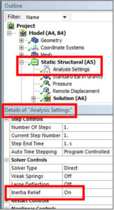
Figure 2: Selection of Inertia Relief in a Static Analysis
The following conditions and limitations, taken from the ANSYS Help Viewer, must be considered:
Inertia Relief – Linear Static Structural Analyses Only
Calculates accelerations to counterbalance the applied loads. Displacement constraints on the structure should only be those necessary to prevent rigid-body motions (6 for a 3D structure). The sum of the reaction forces at the constraint points will be zero. Accelerations are calculated from the element mass matrices and the applied forces. Data needed to calculate the mass (such as density) must be input. Both translational and rotational accelerations may be calculated.
- This option applies only to linear static structural analyses.
- Nonlinearities, elements that operate in the nodal coordinate system, and axisymmetric or generalized plane strain elements are not allowed.
- Models with both 2D and 3D element types or with symmetry boundary constraints are not recommended.
- Loads may be input as usual. Displacements and stresses are calculated as usual.
- Symmetry models are not valid for inertia relief analysis.
Note the need for “just enough” constraint to prevent rigid body motion, and for mass in the model. Settings for an Inertia Relief model will be described in the following example. “Weak Springs” ought to be turned off.
Setup of a Static Structural FEA Model with Inertia Relief
As in Figure 1, a flat surface body has been created and meshed with shell elements. The body contains a circular imprint. A pressure load has been applied to the imprint, directed so that it can lift the body. Gravity pulls down.
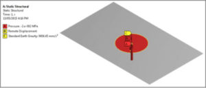
Figure 3: Static Structural Model with a Lifting Pressure Applied
In Figure 3 and Figure 4 a Remote Displacement has been applied to the circular imprint edge, set to zero displacement and rotation in X, Y and Z, and set to Deformable, so that the structure can deform locally. As mentioned further below, constraint at vertices may be preferred.
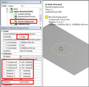
Figure 4: Remote Displacement to Prevent Rigid Body Motion – 6 DOF are Constrained
As a check during post processing, both Force Reaction and Moment Reaction have been measured as in Figure 5 to see that they are virtually zero, as should happen with Inertia Relief.
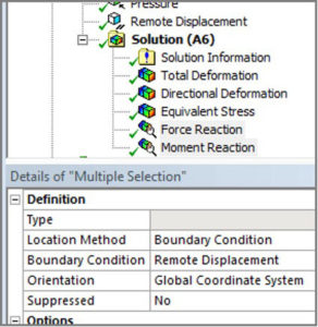
Figure 5: Measure Force and Moment Reactions at the Remote Displacement
Deflection of the structure takes on the form expected, as seen in Figure 6. The structure is pulled up at the center, pulled down by gravity, and pulled down by the Inertia Relief acceleration that is applied in order to make the net applied force match the inertial accelerations that are applied to provide Inertial Relief.
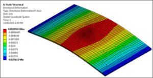
Figure 6: Deformation in Y
At the end of the Solve of the load step, the Output text listing provides information on the Inertia Relief translational accelerations and rotational accelerations that balance the model so that there are no reaction forces:
********* TOTAL LOAD SUMMARY *********
X-AXIS Y-AXIS Z-AXIS
FORCES AT CENTER OF MASS……………… 0.80779E-26 10.189 0.96935E-26
MOMENTS ABOUT ORIGIN………………….-0.57601E-06 0.10340E-24-0.44384E-07
MOMENTS ABOUT CENTER OF MASS…………..-0.76797E-06 0.10340E-24-0.40969E-07
********* INERTIA RELIEF SUMMARY *********
X-AXIS Y-AXIS Z-AXIS
INERTIA RELIEF TRANSLATIONAL ACCELERATIONS 0.12250E-21 0.15452E+06 0.14701E-21
INERTIA RELIEF ROTATIONAL ACCELERATIONS…-0.38801E-04 0.13836E-23-0.74542E-06
****************************************************
*************** FINISHED SOLVE FOR LS 1 *************
This example has virtually zero acceleration in all directions except the Y axis, because the applied pressure is centered on the model. The accelerations are those that balance the applied loading, such that there should be not reactions at the constraints that prevent rigid body motion. They are the accelerations that would be seen in a transient analysis if there was no vibration in the response. Force reaction is virtually zero, as seen in Figure 7:
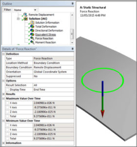
Figure 7: Force Reactions on the Remote Displacement are Virtually Zero
A check should be done on moment reactions, too, as in Figure 8:
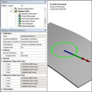
Figure 8: Moment Reactions at the Remote Displacement are Virtually Zero
The reactions are zero because the Inertial Relief Accelerations are balancing the applied loading.
Alternative Constraints | Static Analysis with Intertia Relief
Alternative constraints that prevent rigid body motion could be used, as in Figure 9, in which UY is prevented at three vertices, UX at two vertices, and UZ at one vertex:
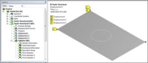
Figure 9: An Alternative Choice of Constraints that Prevent Rigid Body Motion—Three Vertices Involved
Reactions are again virtually zero, and the displacement result is similar but not identical. In Figure 10 the range of vertical displacements is between 0.0 and 0.027502mm, while in Figure 6 the range is -0.025613 and .0020924. The difference in net displacements may be due to the remote deflection affecting shell rotation. Constraining vertices may be preferred in general.
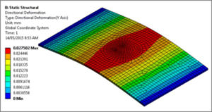
Figure 10: Vertical Displacement with Constraints at 3 Corner Vertices
The same stresses result, as seen in Figure 11:
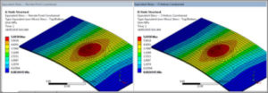
Figure 11: Identical Stresses with Different Approaches to Preventing Rigid Body Motions
Conclusion | Static Analysis with Inertia Relief
Ansys Workbench Mechanical supports Inertia Relief in a static structural analysis when certain conditions are met. Users must turn on Inertia Relief in the Analysis Settings for the static structural environment, and supply just enough constraint to prevent rigid body motions in X, Y, Z, ROTX, ROTY and ROTZ. Reaction forces of zero should result. The Output text listing will report the structure accelerations that are implied by the force imbalances.
Additional Ansys Software Tips & Tricks Resources
-
- Analyzing normal and Tangential Elastic Foundations in Mechanical
- Why Meshing is Crucial for FEA Fluid Simulations Prior to Prototyping
- For support on Contained Fluid FEA Modeling with HSFLD242 Elements
- For Exporting a Deformed Geometry Shape Post-Analysis in Mechanical
- For guidance Multi-Step Analyses in Mechanical
- For Retrieving Beam Reaction Force in a Random Vibration Analysis
- Deploying Ansys Macro Programming vis *USE Command in Mechanical
- For replicating Fatigue Models from Start to Finish in Mechanical
- Setting up Acoustic Simulations of a Silencer
- For a step-by-step guide on 2D to 3D Submodeling in Mechanical
- For modeling Pipe16 Circumferential Stress in Mechanical
- For Support on performing ‘EKILL‘ in Workbench
- APDL Command Objects post-Spectral Analysis
- For Separating DB Database Files from RST Files
- Measuring Geometric Rotation in Mechanical WB
- Explicitly, CAD Geometry Deformation Plasticity
- Offsetting a Temperature Result to Degrees Absolute
- For general guidance on Ansys Post-Processing
- Finally, for basic Ansys Software Installation and License Manager Updates