Ansys Mechanical Workbench | Random Vibration Analysis
Identifying & Retrieving Beam Reaction Forces for Post-Processing
Ansys Workbench (WB) Mechanical provides the ability to perform random vibration analyses, which are sometimes referred to as power spectral density (PSD) analyses, or more simply, spectrum analyses. PSD is statistical in nature and as a result of the solution technique, many results that would typically be available in WB Mechanical for a classic static structural analysis, are not natively available in WB for a PSD analysis. However, some can still be retrieved from the WB Mechanical solver via inserted Command Snippets.
Extracting Force Reaction Results
This document discusses and presents the command language that is available for an analyst to extract force reaction results for beam connections used in WB Mechanical in a PSD analysis. Two primary approaches are given: one to obtain beam force reaction results in the global Cartesian coordinate system and another to obtain the results in each beam’s local element coordinate system. There is also discussion given to obtain results at various confidence intervals (1-sigma, 2-sigma, 3-sigma).
Upfront Modal Analysis
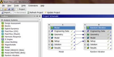
Prior to any PSD analysis, there must first be a modal analysis, of which the solution feeds into the PSD analysis. This connectivity between the systems is first set up on the WB project page, which is illustrated in the figure.
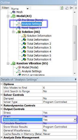
The modal analysis can be performed as usual. However, in the Output Controls of the Modal analysis, the option to output nodal forces must be set to YES, thereby populating the results files with the necessary data to later extract beam forces from the PSD analysis. The other output options are at the discretion of the analyst, depending on what other results are required in post-processing.
Identifying Beam Connections for Post-Processing
Beam connections are created in WB Mechanical under the Connections branch. However, the beam elements are not actually created and assigned element numbers until the solve process. Therefore, it is not possible to know upfront what number is assigned to each beam element and, as shown later, the beam element numbering scheme is pertinent to post-processing the results. To address this, it is necessary to insert a Command Snippet under each beam connection.
Right Mouse Button on Each Beam ;→ Insert → Commands
For each Command Snippet, the following command should be inserted:
BEAM1=_bid
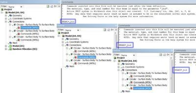
In the above command line, the numeral 1 increments for each beam. As the solver creates a beam, a parameter _bid exists with a unique numerical value that represents that beam. _bid is overwritten once the solver begins creating the next beam. Therefore, the above command is intended to define a numerically unique parameter (e.g., BEAM1) for each given beam that will not be overwritten and can be used for traceability later in post-processing. See Figure 3 below to illustrate the unique sequential numbering of each beam.
Extracting Beam Forces From PSD Analysis (Global Cartesian Coordinates)
After a modal analysis has been setup and connected to a PSD analysis, the procedure to extract force reaction results from beam connections is fairly straightforward. The results obtained using this approach will give results in the global Cartesian coordinate system for the 1-sigma confidence interval. Discussion is given later as to how to obtain results in each beam’s local coordinate system. To proceed in WB Mechanical, insert a Command Snippet in the Solution branch of the PSD model.
Right Mouse Button on Solution →Insert →Commands
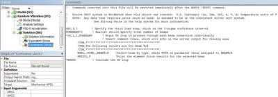
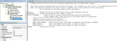
The analyst can then copy/paste the following commands into the Command Snippet, which will execute immediately after the solution is done. An example is illustrated in the figure below. Notice the second command line (NUMBEAMS) where the analyst must specify the total number of beams being dithered (e.g., 3 in this example).
SET,3,1 ! Specify the third load step, which is the 1-sigma confidence interval
NUMBEAMS=3 ! Analyst should specify total number of beams
*DO,i,1,NUMBEAMS ! Begin DO loop to process through each beam connection individually
! Insert comment lines, which will echo in the solver output for viewing ease
/COM,*********************************************
/COM,The following results are for Beam %i%
/COM,*********************************************
ESEL,,TYPE,,BEAM%i% !Select beam by type, where TYPE is parameter value assigned to BEAM%i%
PRESOL,F !Print the element force results for the selected beam
*ENDDO ! Conclude the DO loop
Beam Element Solver Input
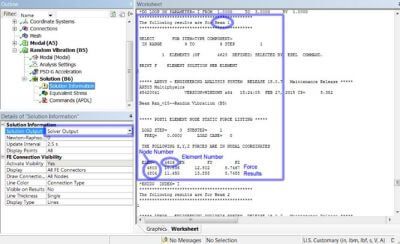
Once solved, the results will then be printed node-by-node, in the global Cartesian coordinate system, for each beam element in the Solver Output, which is available from the Solution Information branch. An example is illustrated below. Because the leading command was SET,3,1, the results are for the 1-sigma confidence interval. There is discussion later for obtaining results at other confidence intervals.
Extracting Beam Forces from PSD Analysis (Local Beam Coordinates)
Similar to the previous option, the procedure again is fairly straightforward. The results obtained using this approach will give results in each beam’s local coordinate system for the 1-sigma confidence interval. Specifically, the results will contain only the force along each beam’s axis (i.e., no side/shear forces will be provided); by WB Mechanical convention, X is the local coordinate axis defined for a beam’s axis. To proceed in WB Mechanical, insert a Command Snippet in the Solution branch of the PSD model.
Right Mouse Button on Solution → Insert → Commands
The analyst can then copy/paste the following commands into the Command Snippet, which will execute immediately after the solution is done. An example is illustrated in the figure below. Notice the second command line (NUMBEAMS) where the analyst must specify the total number of beams being dithered (e.g., 3 in this example).
SET,3,1 ! Specify the third load step, which is the 1-sigma confidence interval
NUMBEAMS=3 ! Analyst should specify total number of beams
*DO,i,1,NUMBEAMS ! Begin DO loop to process through each beam connection individually
! Insert comment lines, which will echo in the solver output for viewing ease
/COM,*********************************************
/COM,The following results are for Beam %i%
/COM,*********************************************
ESEL,,TYPE,,BEAM%i% !Select beam by type, where TYPE is parameter value assigned to BEAM%i%
PRESOL,SMISC,1 !Print the element force results in local X for node I
PRESOL,SMISC,14 !Print the element force results in local X for node J
*ENDDO ! Conclude the DO loop
Solver Output | Element-by-Element
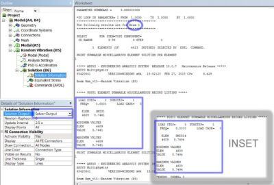
Once solved, the results will then be printed element-by-element, in the Solver Output, which is available from the Solution Information branch. The results will be broken down as SMIS1, which are the results at node I, and also SMIS14, which are the results at node J of each beam. An example is illustrated below. Because the leading command was SET,3,1, the results are for the 1-sigma confidence interval. There is discussion later for obtaining results at other confidence intervals.
Obtaining Results at Other Confidence Intervals
A PSD analysis is statistical in nature. Therefore, the results are also statistical, to include the beam force reaction results. The above methods use the following command, which tells the post-processor that results are desired for the 1-sigma confidence interval.
SET,3,1
Results can also be obtained at the 2-sigma confidence interval:
SET,3,1,2
Or at the 3-sigma confidence interval:
SET,3,1,3
Troubleshooting
The only likely issue that may arise from using these techniques is a situation where the analyst has solved the model already and then later inserted the Command Snippet to the Solution branch of the PSD analysis. At this point, selecting Solve or Evaluate All Results will not update the Solver Output file since a full re-solve is not taking place. Therefore, the analyst will not be able to see the results in the Solver Output file. To address this, the PSD model needs a full re-solve. Do so by:
Right Mouse Button on PSD Solution → Clear Generated Data
The analyst can then re-solve the PSD model to update the Solver Output file with the beam force reaction results.
Conclusions
A PSD analysis is a statistical type of analysis. The initial discussion provided herein gave results in the 1-sigma confidence interval. This means that the reported results are not expected to be exceeded 68.3% of the time for the given input acceleration spectrum. Additional discussion was then given to illustrate how to obtain results at other confidence intervals; 2-sigma (95.4% confidence) and 3-sigma (99.7% confidence).
It was also illustrated how to obtain reaction forces from beam connections either in the global Cartesian coordinate system or each beam’s local coordinate system (but restricted to axial results). If force reactions are desired in all three coordinate directions, but aligned differently than the global Cartesian coordinate system, the RSYS command allows the analyst to rotate results into some other defined coordinate system before printing to the solver output file. The analyst may reference the Ansys Help Menu for further discussion related to the use of this command.