Ansys Workbench Mechanical supports “External Model” – a facility for directly importing an Ansys Mechanical model’s CDB mesh file into Workbench for Post-Processing APDL Models.
This may include subsequent study or general schematics reviews. This feature includes the ability to read a results RST or RTH file that corresponds to the CDB file that has been attached as an External Model. The approach applies to solid and shell models. This article describes an approach with solid elements.
This article reviews steps in creating a CDB file in Ansys Mechanical APDL, and reading in the CDB file in Workbench, plus importing results from an associated RST results file. This permits the Workbench Mechanical environment’s tools to be employed in postprocessing a model that originated in Ansys Mechanical APDL, as well as generating a report to automate generation of data that might be of interest in the appendix to an engineering report. Good quality modern graphics images of models, animations, results scoping, and other features of the Workbench Mechanical interface may be of interest to users.
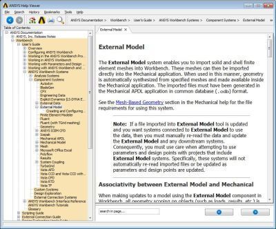
Workbench Mechanical at release 15.0 has a new External Model component system that can take a solid or shell finite element mesh from a CDB file, and generate a solid model with a mesh for use in Workbench Mechanical. Users should review the Ansys v15.0 Help system for information on this External Model feature. It contains information on reading an external model, as well as on rotating and translating the geometry that is imported.
The External Model approach for model review is not an officially supported feature of the Ansys software, so users intended to use this facility must do their own quality control if this feature is employed.
To use this feature, a CDB file that contains a supported mesh type must be generated in Ansys Mechanical APDL. The CDWRITE command of Ansys is used in /PREP7 to generate the CDB file. Arguments are set to generate the mesh, without the geometry data, for example:
CDWRITE, Option, Fname, Ext, –, Fnamei, Exti, Fmat
Writes geometry and load database items to a file
The following example generates a mesh file only (no associated geometry):
CDWRITE,DB,myfilename,CDB
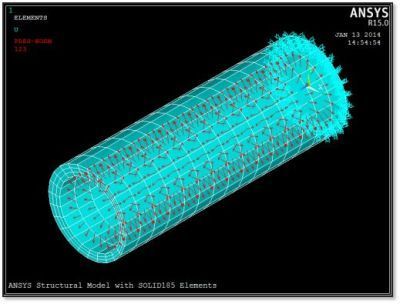
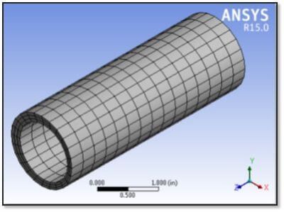
The following example model contains SOLID185 8-node brick solid structural elements subject to pressure loading and to constraint on node movements. It could be solved in Ansys Mechanical APDL, in which case an RST structural results file would be generated in the working directory:
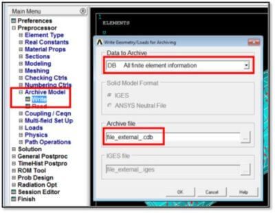
In the Post-Processing APDL Model in Ansys Mechanical, view the interface, and the following menu item will generate a CDB file for the above mesh:
Workbench v15.0 is capable of reading the CDB file of the mesh, fitting a geometry to the mesh, and sending the resulting model of geometry and mesh into Workbench Mechanical for study in that environment, making the various tools of Workbench Mechanical available for further studies on models that originate in the APDL interface.
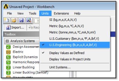
For simplicity, start by setting Units to those employed in the CDB file—the user must know this in advance:
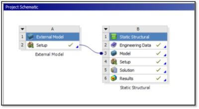
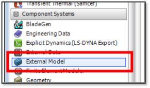
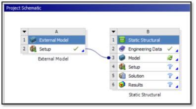
In the Workbench project page, drag an External Model component system into the Project Schematic.
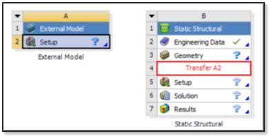
Then, drag an appropriate analysis system into the Project Schematic, such as the Static Structural. Next, drag the Setup cell of the External Model to the Model branch of the Static Structural system:
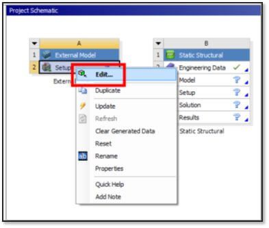
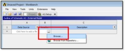
Right-click the Setup cell of the External Model system, and choose Edit:
A Data Source window opens; Browse to the CDB file of interest:
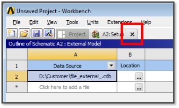
Find the CDB file for import, click it, and click Open. Now, close the window by clicking the X:
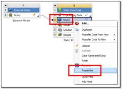
Click the linked Model cell in the Static Structural system, right click, and choose Properties:
In the Properties window that opens on the right, choose the Length Unit as in the CDB file, tweak the Tolerance Angle if needed to aid in fitting geometry faces to the mesh in a complex model, and indicate whether the analysis is 3D or 2D. Nodal Components will be included by default and might be desired to use as Named Selections:
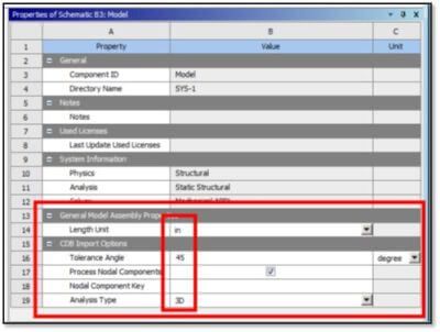
Note the “Process Nodal Components” entry above. Nodal components in the APDL model become Named Selections in Workbench Mechanical, corresponding to faces in 3D. To postprocess results on these components, ensure the check mark is set as in the figure above.
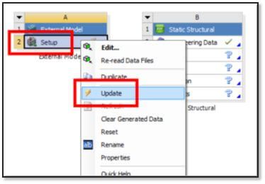
Now, the External Model can be updated by clicking Setup, right-clicking, and choosing Update.
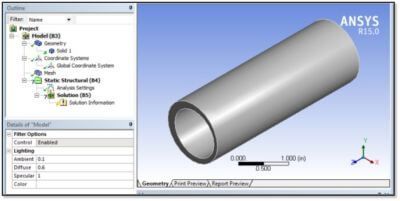
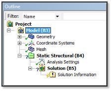
As you’ll see, geometry will have been fitted to the mesh, and the Static Structural system can be opened to commence work:
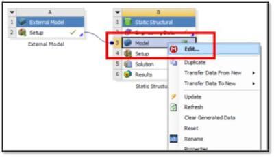
Now, right-click Model in the Static Structural system, and choose Edit:
The Workbench Mechanical window is exposed. Elements from the CDB file are present, as is the geometry that was fitted to the elements. The materials used are not those of the CDB file—they are taken from the Engineering Data branch of the Static Structural system, and defaults will be assigned. Loads are not read from the CDB file, either. Note that the Static Structural system in the figure below is not ready to be solved—neither loads nor boundary conditions are present.
Here, we find the mesh that came from the CDB file in this example:
As stated neither loads nor materials are imported from the CDB model.
At this point, a user could assign Engineering Data materials to geometric entities. In addition, place loads and boundary conditions on the model, and solve the FEA model. Alternatively, the CDB model’s RST results file can be imported, which will be illustrated next.
The model indicates that it is not ready to be solved because of the absence of loads and boundary conditions:
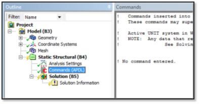
First, place an empty APDL Commands Object in the Static Structural environment. Its presence lets Workbench Mechanical assume loading exists, so that a user can load results from an RST file. This is seen in the figure below:
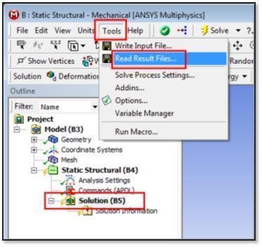
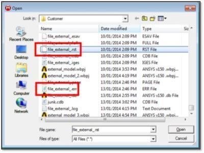
Highlight the Solution branch, and go to Tools > Read Results Files… to access the RST file:
Next, the RST file is selected, usually from the working directory in which the CDB file was found. Note that the .ERR error file for the model must exist there. If none exists, a dummy file with the correct job name can be created there, using the .ERR extension.
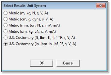
Now, the above window closes when the Open button is clicked. This is followed by a dialog box requesting that the user indicate the Units employed… the user must ensure that the correct choice is made, and click OK:
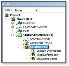
With this done, a user can begin to request results below the Solution branch.
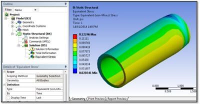
Additionally, branches for results such as Deformation or Stress might be inserted:
Then, a request to Evaluate All Results is made next:
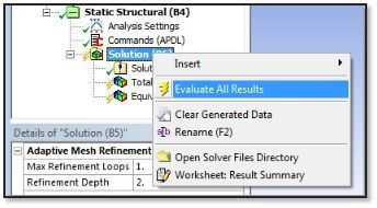
Users can employ the various tools of Workbench Mechanical to review results from the RST file.
If desired, a user can work directly from an RST file, without a CDB or database DB file. Start Post-Processing APDL Model in Ansys Mechanical, go to /POST1, and use the File command to indicate an RST results file of interest. Use the SET command to read a result of interest—this works for RST files. By default, in APDL, contain element and node data for the model. Go to /PREP7 and use CDWRITE to write a CDB mesh file within Ansys Post-Processing.
In addition, Workbench can now read the CDB file, fit geometry to the mesh, and read the RST file (the .ERR file must exist—create a blank jobname.err file if necessary matching the CDB file). Workbench Mechanical can now postprocess a model for which only an old RST file exists. (RST files generated by Workbench Mechanical will not contain this mesh data, for size efficiency.)
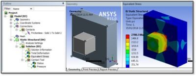
As seen in the figure above, this approach can display degree of freedom data (displacement in a structure). It can display stress and strain if they exist in the RST file. Probes cannot be created for reaction forces and forces across contacts. That is, since no such objects exist in the Outline—APDL Commands Objects would review such things.
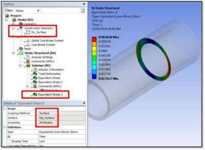
During model review, Construction Geometry can be used to create Paths and Surfaces to be used in postprocessing objects. In the figure below illustrates stress on a surface object.
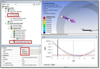
A Path can be created by various techniques. In addition, the corresponding results or linearized results shown on the path, as seen below.
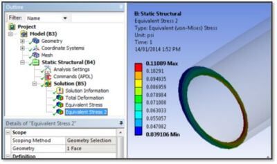
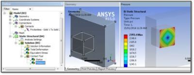
Results can also be presented as scoped onto selected geometry:
An imported CDB file could contain contacts. If the RST file contains contact results, these can be inspected in the Workbench Mechanical model. The following figure shows two bodies in contact. A contact pair is created as a result of geometric proximity of parts. This does not reflect what contacts existed in the CDB file. In this example, the contact pair has been given the same “Type” as that in the CDB file.
They have been squeezed together in the Post-Processing APDL Model in Ansys Mechanical:
Then, Contact Tool can be created for a contact pair, and if the “contact” surface of the pair in the CDB file contains a result. As a result, the contact can be reviewed in Workbench Mechanical:
As we’ve reviewed, Workbench Mechanical can use External Model to read an Ansys Mechanical APDL model’s CDB file for a mesh. Specifically, as written by the CDWRITE command for typical solid and shell elements.
Geometry can be fitted to the mesh, and Workbench Mechanical can receive the meshed model. An associated results file (RST file for structures) can be read into Workbench Mechanical. As a result, the tools of Workbench Mechanical can be used for model review.
Generating a Report within Workbench Mechanical can produce extensive model information of potential interest. This can be tedious to generate manually.
Fortunately, many creative applications for this External Model capability can be developed. Consequently, providing another option Mechanical to review the results of Ansys Mechanical APDL models. Note that inside Ansys Mechanical APDL, the UPGEOM and UPCOORD commands can be used to move nodes. Specifically, that of an unstressed model into the positions, calculated by a SOLVE command.
In addition, a factor can be applied to the movements, using values other than a default 1.0. If a negative factor of -1.0 is used, nodes are moved into a position. When loaded, a structure moves into the position of the original geometry (in a linear analysis).
This might be used, for example, to find how to shape a structure so that it moves into a desired geometric shape after loading. Workbench Mechanical and FE Modeler could be used to find the geometry that fits that pre-deformed mesh. A more complex procedure could be used if large deflection effects were relevant for accuracy. If needed, select the following link for advanced finite element analysis consulting services.
Ultimately, this External Model approach permits the tools of Workbench Mechanical to be used to examine the results of old Ansys APDL models with the various advantages of the Workbench interface.