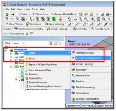
A user can place a Path along an Edge in WB Mechanical, or between two points. The Two Points approach can use vertices, or model face locations. To start with creation of a Path (between nodes), a model needs a Construction Geometry branch:
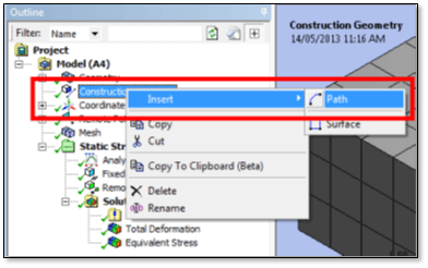
One or more Paths or Surfaces can be inserted into the Construction Geometry branch:
The user must enter Details for a new Path to complete its definition. The path should be named appropriately.
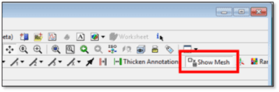
Before proceeding, if the use of two nodes to define a Path is wanted, it helps to make the mesh visible:
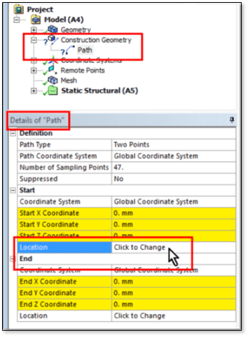
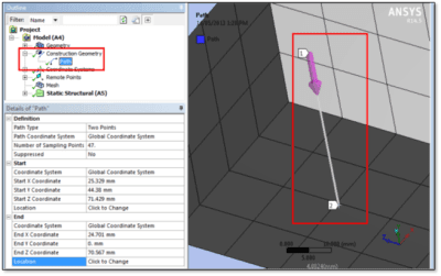
After clicking on the Path entry in Construction Geometry, a Path Type based on “Two Points” can be selected. That requires definition of the Start and the End points for the path:
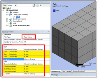
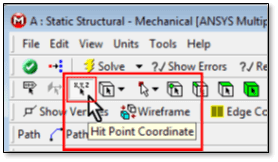
“Two Points” typically selects two vertices. A toolbar icon can be used to select locations on faces in the model:
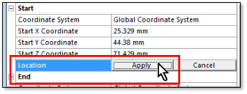
Each of the two points can be defined in turn. First the Location of the Start is chosen:
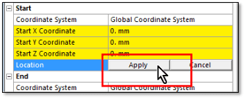
The “Click to Change” box changes to provide an Apply button:
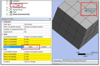
Then, go to the graphics window to click on a location for the first point on the path. Rotate and zoom the model so that the element faces where the first node is to be chosen are visible, as illustrated below.
Click very close to the first node to be chosen, zooming as required:
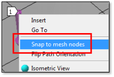
After clicking on the location on the surface, right-click the mouse, and select “Snap to mesh nodes”…
Then, click the Apply button for the Start point:
Now repeat for the node at the other end of the path. Rotate the model as needed. Click on the Location box for the End point so that Apply appears:
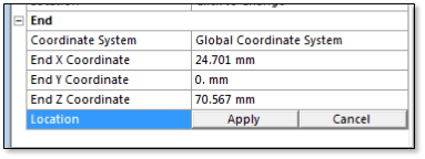
Now click close to the location of interest for the End point, right-click and choose “Snap to Mesh Nodes”, and go back to the Location box and click the Apply button. The path should appear as desired, travelling between two nodes on exterior faces of the model:
Once the path exists, results of interest can be mapped onto the path for postprocessing purposes, including linearized results that may be of interest when satisfying design codes.
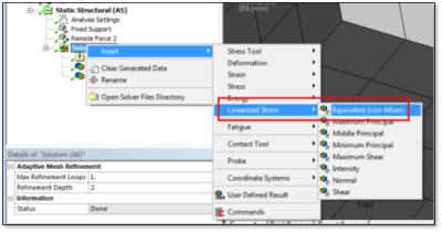
A linearized stress can be inserted below the Solution branch for an environment of interest.

The Path of interest can be chosen by name from a drop-down list in the Details for the linearized result:
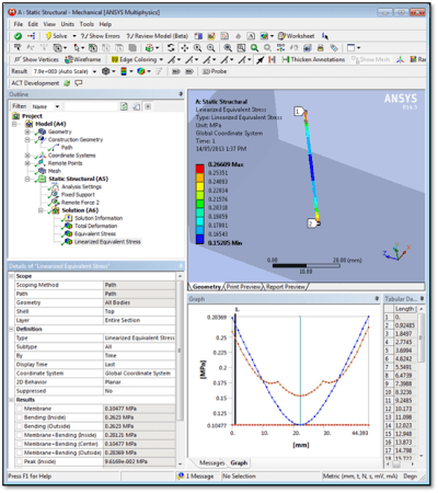
With a path for data mapping chosen, right-click at the Solution branch, and choose “Evaluate All Results” to see the linearized stress plot and data.
The results of the path linearization can be observed, and optionally promoted to parameters, as needed:
Many paths can be created, and for any given path, many linearized results can be defined and observed.
There are tools in Ansys Workbench Mechanical that permit Paths for stress linearization to be created between node pairs, not just between pairs of vertices, or along edges in a model. Turning on a mesh view with “Show Mesh”, and using “Snap to Mesh Nodes” makes it possible to position the desired path Start and End point so that the path terminates at existing nodes in the model.
Objects for reviewing linearized results on paths can be inserted for postprocessing at the Solution branch in the Workbench Mechanical Outline. Various solution results can be mapped onto each of the paths created in a model. The stress linearization output should help in the satisfaction of various design codes of interest to a user.
The latest Ansys Software releases to support with construction geometry
Ansys Mechanical Workbench is a top-tier finite element solver with capabilities to enhance your modeling in the areas of structural, thermal, acoustical, transient, and nonlinear behavior.
Ansys LS-DYNA simulates the response of materials to short duration severe loading. Today, it is the single most used explicit dynamics simulation program worldwide. Best suited for highly technical users.
Ansys EnSight is the market leader for data visualization. Its post-processing tool includes models with more than hundreds of millions of cells, providing engineers with insights unavailable elsewhere.
Ansys Motor-CAD is a specialized electric machine design tool that allows for quick multiphysics simulation over the entire torque-speed working range.
Ansys HFSS simulates 3-Dimensional full-wave electromagnetic fields for accurate and rapid design of high-frequency and high-speed electronic components.
Gain quick, accurate electronic hardware life predictions with Ansys Sherlock, the only PoF (Reliability Physics/Physics of Failure) software that provides insight at each the system, board, and component levels.
A comprehensive solution for designers, engineers, and analysts that spans the full workflow, from design for additive manufacturing (DfAM) to validation, process simulation, and material exploration
Component-level and system-level simulations are provided by the extensive range of photonics simulation to improve performance, lower the price of physical prototyping, and shorten time-to-market.
Ansys Icepak provides specialized electronic cooling solutions that utilize the industry leading CFD solver for T&F flow analyses of integrated circuits, PCBs and electronics.