Bonded Contact Pairing in Ansys Mechanical Workbench
The Ansys Mechanical Workbench Platform has many settings for contact between surface body (shell) faces. This article examines a setup to employ with bonded contact pairing across a gap between surface body midplanes in large deflection nonlinear analysis.
Creation of a Bonded Contact Pair Between Surface Body Faces
If surface bodies are created on the midplane of the thin solids that they approximate, the surface bodies that lie on top of each other will have a gap between the midplanes. The gap size will often be greater than the tolerance used in the automatic creation of contact pairs when geometry is imported into Workbench Mechanical. Either the tolerance employed in the creation of contact pairs will have to be modified. In addition, the contact pairs regenerated, or manual contact pairs will need to be created between overlapping surface bodies.
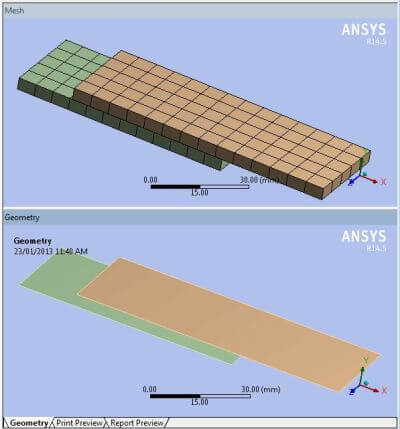
The figure above shows a pair of surface bodies, and the mesh that results when they have been meshed with shell elements. The shell thicknesses entered for the surface bodies in the model close the gap between the surface bodies so that they touch on a pair of faces. In this example, there is a 4 mm gap between the surface bodies.
Setting a Thickened Viewport of Shell Elements in Ansys Mechanical
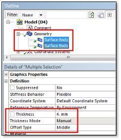
These surface bodies are intended to lie on the midplanes of the shell elements. So, in the example, both surface bodies have been set to a thickness of 4 mm, as illustrated in the figure below to the right. The upper image in figure above shows a thickened view of the shell elements, so that closure of the gap is illustrated.
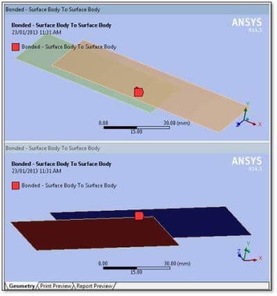
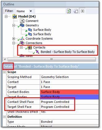
As can be seen in the first figure above, the “Top” of each of these surface bodies happens to face in the –Y direction. That is, in the global coordinate system. Consequently, the Contact and Target surfaces do not face each other. To get the contact pair to work, the Details settings for Contact Shell Face and for Target Shell Face for the contact pair can either be left as “Program Controlled.”
Or, alternatively, set by the user to choices of Top and Bottom. This way the red Contact face and the blue Target face will look towards each other. This is required to get the resulting target and contact elements in Ansys to attach to each other without implied penetration and solution failure.
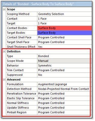
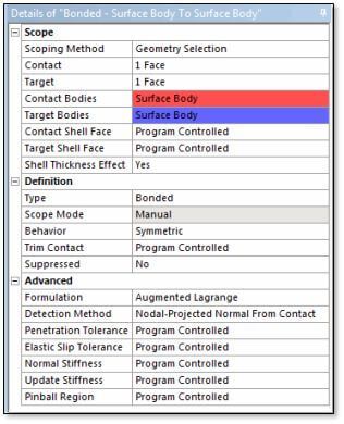
Continuing with the Details definition of the contact pair, the contact will be set to Bonded. This permits both Symmetric contact with penalty-based formulations, and Asymmetric contact with all formulations. In the present example, a Symmetric behavior is selected.
Augmented Lagrangian and Penalty-Setting in Ansys Mechanical
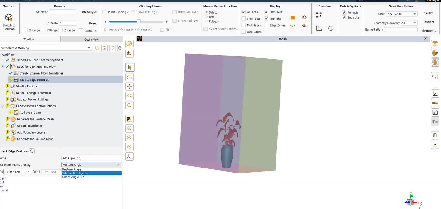
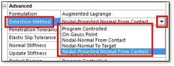
In the figure below, the Formulation has been set to “Augmented Lagrangian” although a Penalty setting has also been satisfactory in testing. The Detection Method has been set to “Nodal-Projected Normal From Contact.” This was found to produce deflection and stress plots that were preferable to those resulting from alternative settings.
The figure below shows the Detection Method choices in a drop-down listing. Users may want to experiment with the consequences of these various choices. The Projected choice is a relatively new addition to Ansys.
Creating a Y Deflection with Nodal-Projected Normals | Ansys Mechanical
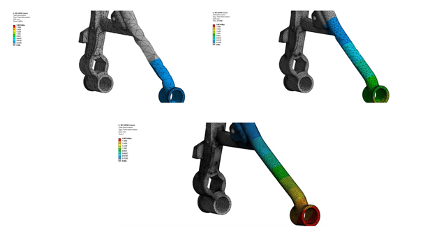
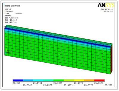
The figure below shows equivalent stress and Y deflection with Detection Method “Nodal-Projected Normal From Contact”.
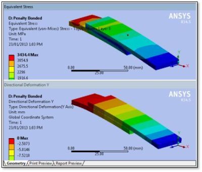
Contrast this with the figure below, the consequence with “Program Determined”. The deflection plot has similar amplitude, but the stress does not show the figure above result. Where, in contrast, the “thick” region stresses are higher at outer layers, and smaller at the bonded interface. In effect, this acts like the mid-plane of an 8mm thick shell.
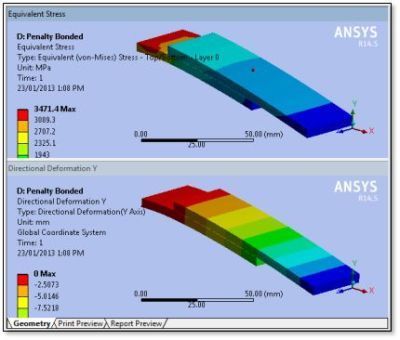
For this reason, the “Nodal-Projected Normal From Contact” of Figure 7 will be preferred.
Other Detail settings in the Advanced section in Figure 5 have been left as Program Determined in this example. However, users may prefer to increase the Normal Stiffness factor, and to set a Pinball Region manually.
Loading on the Model
The edge at one end of the surface body pair was fixed, and a force was applied to the other end.
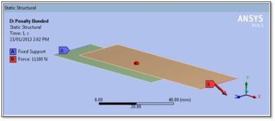
The force has components in the Global X and Y directions:
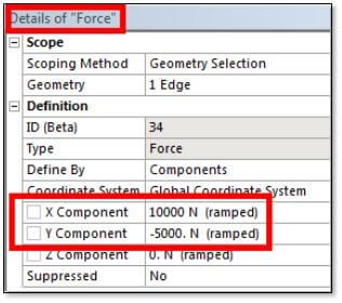
The Analysis Settings for this example were set to perform a Large Displacement analysis. Non-default Output Controls were set to output contact information, making it feasible to measure the force transmitted across the contact pair in the model. Force Results probes are not satisfied until Contact Miscellaneous is set to “Yes”.
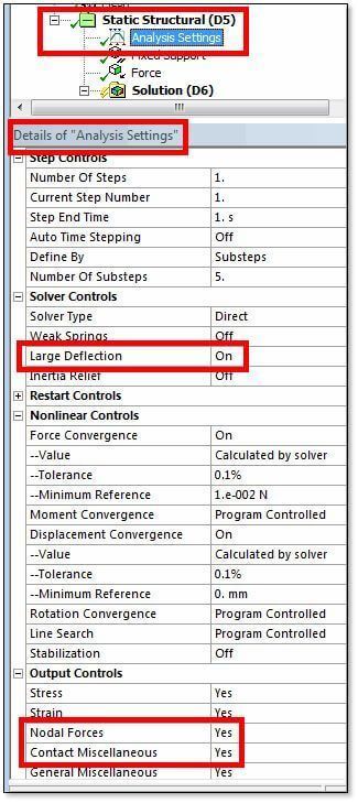
As is often the case in finite element analysis (FEA), if users are unsure whether a Large Displacement analysis is warranted, a model can be run. With Large Displacement activated (or if Large Displacement was not required) convergence usually adds just one additional iteration.
Outputs from the Example Model
Many postprocessing objects were added to the test model, in order to observe the consequences of contact pair options. This includes deflections, stresses, force reactions across the contact, and Contact Tool outputs.
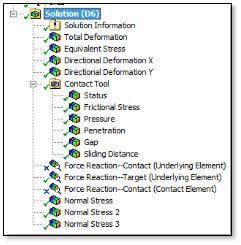
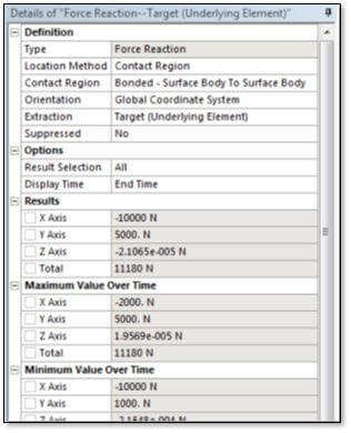
In the figure above, two of the three Force Reaction objects were suppressed—“Contact (Underlying Element) choice produced near-zero numbers. In addition, Contact (Contact Element) had unsatisfied inputs in most cases. The “Target (Underlying Element)” choice produced a force result matching the edge input forces applied.
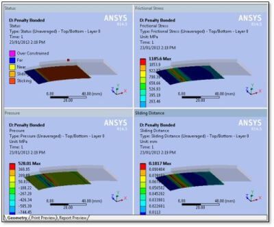
Contact Tool results were requested on the “Contact” side only. Although a symmetric bonded contact was requested, a result is only plotted on the lower body. Because the Top of the lower body faces the –Y direction, results are plotted on the -Y side face of the thickened view of the lower surface body. The figure below shows Status, Frictional Stress, Pressure and Sliding Distance. The pressure and sliding distance values are non-zero because of the finite penalty stiffness values in the contact elements.
Conclusions | Bonded Contact Between Shell Faces
After a survey of settings for a contact pair, that is between the faces of two surface bodies, observing stress, deflection, contact. And consequently, force reaction resulting in a large displacement model. It was found that satisfactory results were seen when a face-to-face contact pair between the surface bodies was set to Bonded, Symmetric.
In addition, a Detection Method of “Nodal-Projected Normal from Contact” was also realized through these computation sequences. The force across the contact pair could be measured with a Force Reaction probe for the contact pair. With Extraction, simply set to “Target (Underlying Element)”.
Setting for Shell Thickness Effect in Ansys Workbench
The above figure setting for Shell Thickness Effect did not have a substantial effect on results. Yet, was set to “Yes” to capture the offset of the contact surface from the midplane, which might have a stronger effect with thicker shells.
The Behavior entry in the Definition section could have been “Asymmetric” or “Program Controlled” but was set “Symmetric.” In effect, the finite size of the contact and target elements would leave less disconnection at the ends of the contact zone. And ultimately, would cope better with variant element sizes on the contact and target faces.
Users could try optional settings for many of the Details in the contact pair settings, including assignment of the Contact Body and the Target Body. In addition, manual assignment of the Contact Shell Face, Target Shell Face, and Pinball Region size. In the present example, adequate results were realized with many Program Controlled settings.
Tightening Nonlinear Controls Settings for Force Convergence in Ansys Mechanical
Convergence did not become an issue with these settings for the present Large Displacement example. The Analysis Settings had tightened Nonlinear Controls settings for Force Convergence and for Displacement Convergence in this example. However, these are generally at the discretion of the user.
Users should keep in mind that may of the complications of contacts with Surface Bodies and their shell elements are avoided. Particularly, with Thin Surface method solid meshing with SOLSH190 elements of solid bodies. For more on operation engineering best-practices.
Additional Ansys Software Tips & Tricks Resources
-
- Analyzing normal and Tangential Elastic Foundations in Mechanical
- Why Meshing is Crucial for FEA Fluid Simulations Prior to Prototyping
- For support on Contained Fluid FEA Modeling with HSFLD242 Elements
- For Exporting a Deformed Geometry Shape Post-Analysis in Mechanical
- Moreover, for guidance Multi-Step Analyses in Mechanical
- For Retrieving Beam Reaction Force in a Random Vibration Analysis
- Deploying Ansys Macro Programming vis *USE Command in Mechanical
- For replicating Fatigue Models from Start to Finish in Mechanical
- In addition, setting up Acoustic Simulations of a Silencer
- For a step-by-step guide on 2D to 3D Submodeling in Mechanical
- For modeling Pipe16 Circumferential Stress in Mechanical
- For Support on performing ‘EKILL‘ in Workbench
- APDL Command Objects post-Spectral Analysis
- For Separating DB Database Files from RST Files
- Measuring Geometric Rotation in Mechanical WB
- Explicitly, CAD Geometry Deformation Plasticity
- Offsetting a Temperature Result to Degrees Absolute
- For general guidance on Ansys Post-Processing
- Finally, for basic Ansys Software Installation and License Manager Updates